![[Paul Ruby Amplifiers]](RubyAmplification.gif)
NOTE: This page is obsolete.
Please see the new
pro pedal board page.
I'm finally finished building a very high quality pedal board (since good ones cost $350).
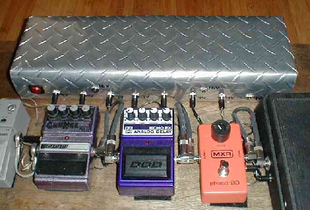
A 12"x24" sheet of heavy aluminum tread plate was folded into a chassis 17"x5"x3" to house the electronics.
It's bigger than it needs to be but it's a great place to step into the crowd's face!
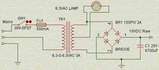
The power supply has 4 separate 9V regulators to supply 8 power jacks.
Also has 2 separate 16V regulators for odd-ball pedals.Be sure to check out Aron's Stomp Box Forum over at Firebottle to get info from real stomp box experts! I wish I had been there before building my board. Mine came out great, with no hum but there are some great ideas over there.
contents
- Gallery
- Electronics
- Printed Circuit Board
- guts are based on the spyder
Gallery of the Finished Product
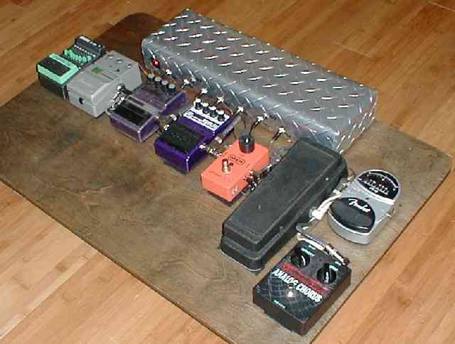
Check out the results first. It came out great with absolutely no hum and solid as a rock. (By the way, I recently installed a bamboo, yes, bamboo floor in my house. Bamboo has the best durability rating of any hardwood I checked out and it looks great!)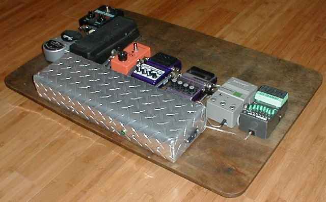
The large empy space is where my Mesa Nomad foot pedal resides. There's a lighted power switch on the left in the picture below and the EIC power connector is on the right in the picture above. The board is 1/2" birch veneer hard plywood, 30"x20" with six large rubber feet for stability. Large velcro squares hold all the pedals to the board.
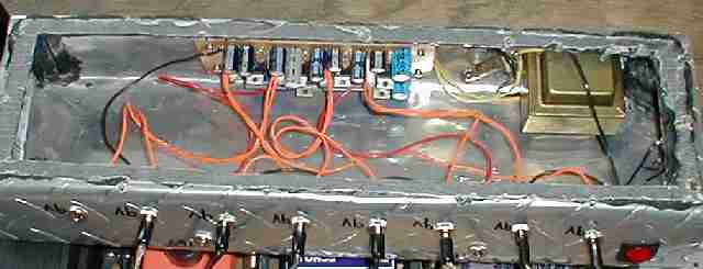
Unfortunately, I don't have a sheet metal break. The tread plate was bent on my garage floor using a slab of plywood on top, which I stood on, while bening up the sides. As such, the corners are very rounded. The smaller, half inch lips at the seams were bent with a little hand tool made for the task. From the inside, all the seams are sealed with black caulking. This was mainly to keep in light from the pilot in the front. The bottom of the chassis also has a layer of black caulking for a good fit to the board.
The guts below show the circuit board, tranny and pilot lamp. Black caulking covered with wax paper forms a gasket on the botttom lip.
Electronics
There's nothing special about the electronics other than being somewhat over-designed to ensure no hum. Four separate 9V regulators are used to supply eight 9V sockets. Here's the basic regulator circuit. I chose to just buy a bunch of 7805 regulators and then alter the voltage with a zener (D1 is a 3.9V zener). You could choose to get 7809 regulators to save a bit of space and cost.The raw input voltage is 18V from the tranny and bridge rectifier. Since there are four separate regulators, the current in each one is limited to ~150mA by R1, 50 ohm 2W. R1 also ensures the regulator will seldom ever need to dissipate much power. As such, there's no need for a heat sink. Worst case, the regulator must dissipate only about 2W. A gob of capacitance, plus some RC filtering at the output yields a rock solid 9V.
If you happen to have an odd pedal or two that need a different voltage, you can change the above circuit in one of the regulators to deliver up to ~16V regulated. Voltage is altered via the zener diode. Output is 5V plus the zener voltage. Note that R1 must change for different output voltages. For example, to get 16V, you can't afford any drop prior to the regulator and R1 should be 0 ohm. Roughly figure R1 to drop the voltage to the regulator down to 2V above your output voltage under full load (100 to 200ma).
A suggestion from R.G. Keen over at Aron's stomp box forum is to add a 1K resistor in series with the output to simulate a near dead battery. I haven't done this but feel free to experiment!
Another suggestion from Aron's forum is to use a separate tranny for each regulator to break the grounds between pedals, thus avoiding ground loops. I've had no trouble with mine but this is something to consider. My tread plate chassis is grounded and all the power sockets are solid metal, thus grounded. The OUTER connection of my sockets is ground with 9VDC on the inner tip. This dictates that my power cables running to the pedals are hand made to reverse the tip and ring connections such that the pedals get 9VDC on the outer ring and ground on the inner tip.
The raw supply comes from a 3A, 6.3-0-6.3VAC from Radio Shack. A bridge rectifier across the full secondary yields 18VDC, filtered by 4700uf.
Printed Circuit Board
Although easy enough to build on a perf board (which is what I did), here's a PCB layout. Six regulators are shown. The resistors are installed vertically to save space. Note the PCB has two filter caps for the raw 18V, though the schematic shows one. There was room... The following is just for reference, not likely to print at the actual size. If you want to do your own, I suggest you draw up your own, but feel free to use the same basic layout to save some time.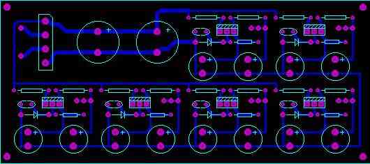
ruby amplification is not associated with ruby tubes
content & layout © copyright ruby amplification 2002
all rights reserved
content & layout © copyright ruby amplification 2002
all rights reserved